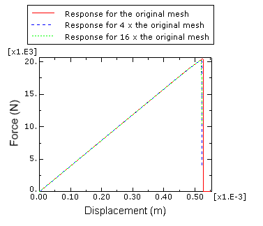

This leads to the undamaged response, with complete failure (D=1) the stress is 0 and in between a fraction of the stress will remain. The stress that would have been there without damage is multiplied by (1-D) to calculate the stress including damage. This can range between 0 (no damage) and 1 (complete failure). Within Abaqus, damage is modelled using a scalar damage parameter, D. With this option, damage will initiate when the maximal principal stress exceeds the value given.ĭefining damage – damage evolution By specifying damage initiation, you do not yet define how the material changes due to damage. Damage initiation is defined as part of the material properties, using damage for Traction Separation laws => Maxps Damage.
#Crack propagation in abaqus cae crack
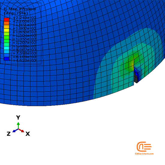
Compared to criteria based on nominal stress or strain, using the principal stress or strain has the advantage that the crack plane can be perpendicular to the direction of the maximum principal stress, making it solution dependent. Different criteria are available for damage initiation, in this case the maximum principal stress criterion will be used. Half of the gear is modelled, for reasons of symmetry.ĭefining damage – damage initiation To model crack propagation in Abaqus both damage initiation and damage evolution need to be taken into account. Linear brick elements are used (quadratic elements are not available for XFEM). Partitioning is only used to allow a finer mesh in the region where the crack will develop compared to the rest of the gear.

Meshing is much simpler, because it is not necessary to partition an initial crack or circular regions around the crack tip. Only in this case, no crack will be present initially and it will develop based on the loading. As an example, loading will be applied to a gear, similar to the stationary crack example.
#Crack propagation in abaqus cae how to
In this blog I will explain how to model crack propagation using the surface-based cohesive behaviour approach and XFEM. In this case, enrichment terms are added to the normal displacement interpolation, so a crack within an element can be described. When the eXtended Finite Element Method (XFEM) is used, this is not necessary. When using one of these methods with conventional FEM, the location of the crack needs to be prescribed beforehand. Abaqus offers different techniques to simulate crack propagation, including surface- and element-based cohesive behaviour and the virtual crack closure technique. In a previous blog I showed how to model a stationary crack and calculate the J-integral to determine whether the crack propagates. Simuleon FEA Blog Modelling crack propagation using XFEM Posted by Dolf Broekaart on 10:00:00 AM


 0 kommentar(er)
